Platform capabilities
One licence. One interface.
Zero software-switching.
From classifying a billion-point cloud to generating finished CAD plans and engineering reports — inside a single session, without exporting to another application.
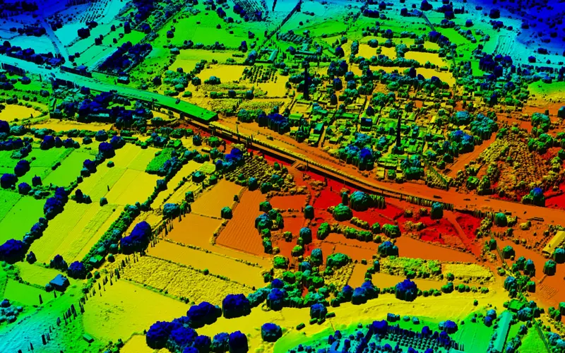
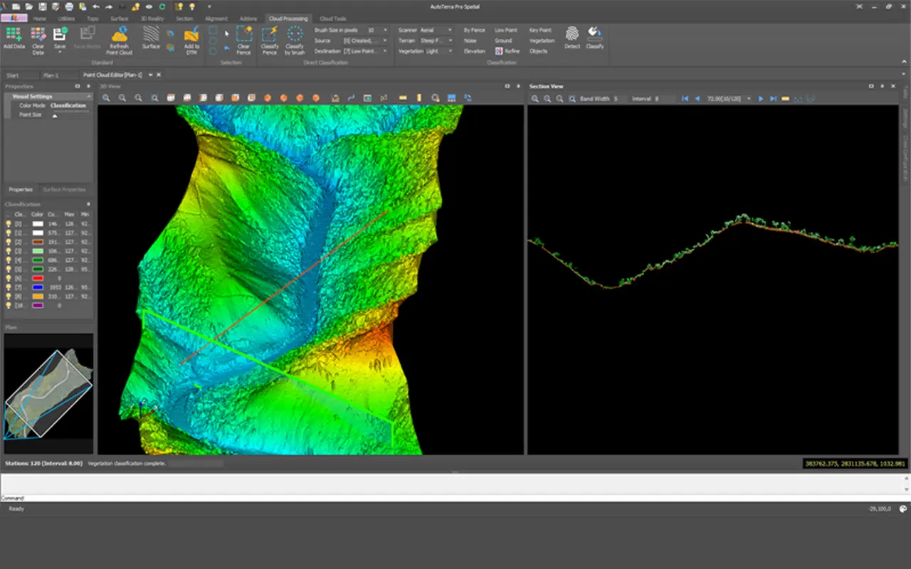
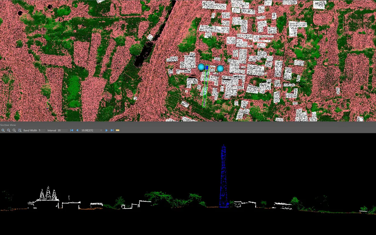
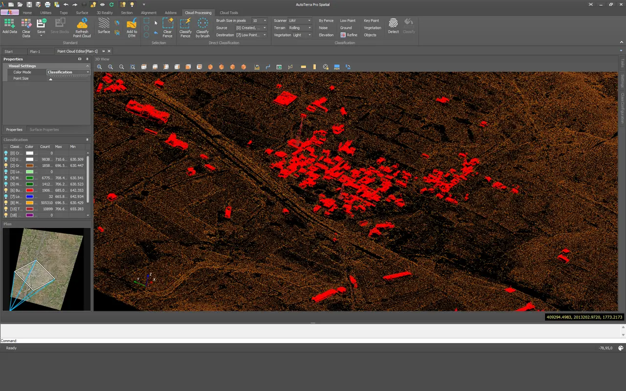
LiDAR point cloud processing
GPU-accelerated classification, object detection, vegetation analysis — interactive in full 3D at any dataset size.
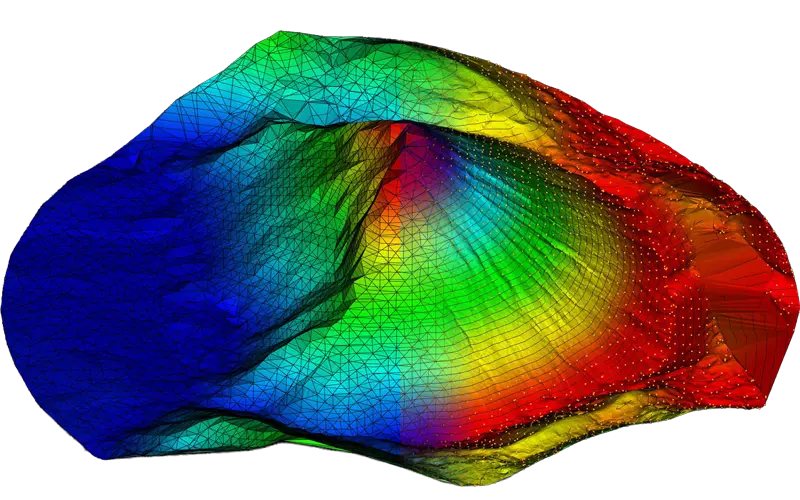
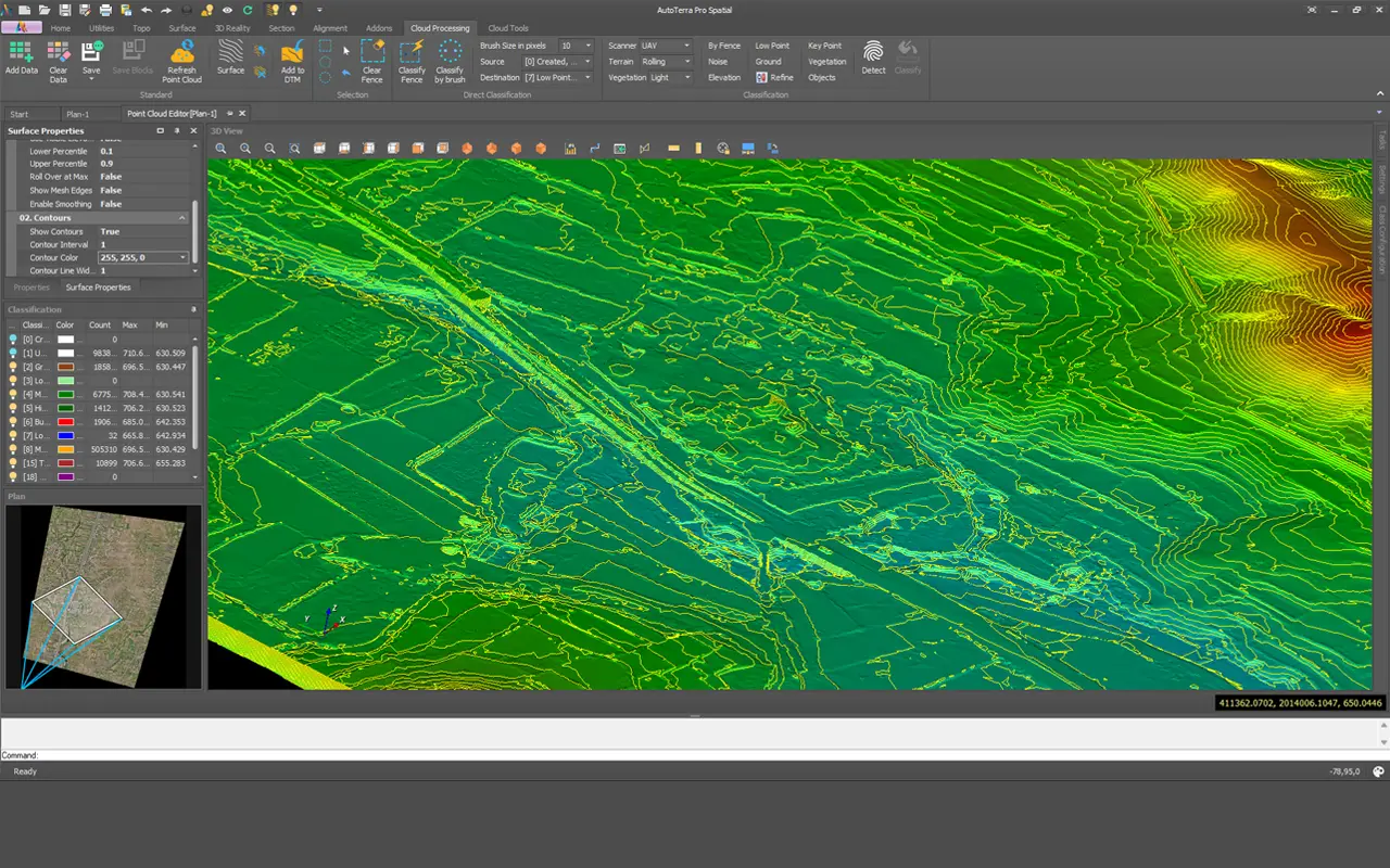
Surface & terrain modelling
TIN surfaces, contours, slope analysis, volumes and cross-sections — from raw survey or classified point cloud.
GIS-native CAD environment
Full CAD drafting with live GIS layers, online maps and survey data coexisting in the same project workspace.